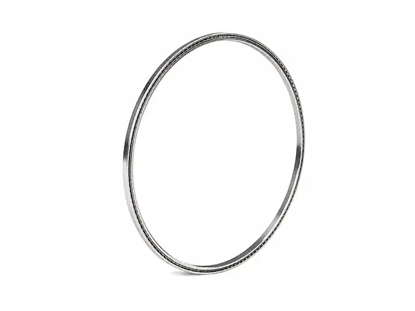
Super Thin Section Angular Contact Ball Bearings
Ultra-compact precision motionOnly 2.5 mm axial width with a 3.0 mm radial cross section. Designed for lightweight, corrosion-resistant and space-limited mechanisms requiring combined radial and one-direction axial load capacity.
Product family: Super Thin Section Angular Contact Ball Bearings
Standard range: Bore 35-170 mm | OD 41-176 mm | Width 2.5 mm | Radial cross section 3.0 mm
Super Thin Section Angular Contact Ball Bearings Overview
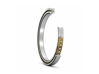
CHG super thin section sngular contact ball bearings use a type A raceway geometry with a reduced shoulder on one side of the inner or outer ring. This geometry allows a larger ball complement within an exceptionally small cross section, supporting radial load and axial load in one direction.
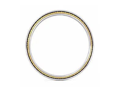
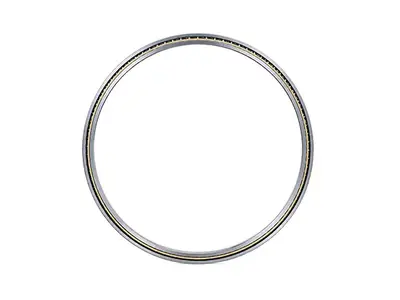
The cross section remains nearly constant as bore diameter increases, helping designers enlarge hollow shafts or cable passages without a proportional increase in bearing envelope and mass. For axial loads in both directions, two bearings should be mounted as a matched pair.
Design Features and Benefits
2.5 mm ultra-slim width reduces axial installation space and total mechanism weight.
Large bore-to-section ratio supports hollow-shaft, cable-routing and compact motion-control designs.
Type A geometry carries combined radial and one-direction axial loads; paired sets provide bidirectional axial positioning.
Stainless-steel rings and balls improve corrosion resistance in moisture and selected clean environments.
Low mass and low rotational inertia support sensitive positioning and intermittent motion.
Custom preload, clearance, precision, lubricant and hybrid ceramic-ball options are available after application review.
Load Direction and Bearing Arrangement
A single Type A bearing supports axial load in one direction only. The bearing requires an applied thrust component to establish the intended contact condition. Where reversing axial load, moment rigidity or controlled axial position is required, use a paired arrangement selected according to the application.
Load Direction and Bearing Arrangement Parameter Table
| Arrangement | Axial load | Rigidity | Recommended use |
|---|---|---|---|
| Single | One direction | Standard | Compact radial + unilateral axial support |
| Back-to-back (O) | Both directions | Higher moment rigidity | Rigid positioning and overturning moment |
| Face-to-face (X) | Both directions | Better tolerance of misalignment | Shorter effective span and installation-error tolerance |
| Tandem | Same direction | Higher axial capacity | Larger one-direction thrust |
Standard Technical Specifications
| Bearing type | Super Thin Section Angular Contact Ball Bearings |
|---|---|
| Bore range d | 35-170 mm (1.3780-6.6929 in) |
| Outside diameter D | 41-176 mm (1.6142-6.9291 in) |
| Axial width B | 2.5 mm (0.0984 in) |
| Radial cross section H | 3.0 mm (0.1181 in) |
| Maximum fillet radius F | 0.25 mm (0.0098 in) |
| Standard material | stainless steel |
| Configuration | Open bearing; full complement or 1/16 in spacer balls |
| Load capability | Radial + axial load in one direction; bidirectional axial load by pairing |
Applications
Robotic joints, end-effectors and compact rotary axes
Satellite mechanisms, optical payloads and camera gimbals
Inspection, measuring and precision positioning equipment
Medical instruments and compact diagnostic mechanisms
Semiconductor and clean motion-control modules
Light and medium duty mechanisms with slow or intermittent rotation
Application boundary
This series is intended primarily for precision positioning and light-to-medium duty mechanisms. Continuous high-speed, shock-load, vacuum, extreme-temperature or high-cycle applications require a dedicated engineering review.
Selection and Installation Guidelines
Define radial load, axial load direction, overturning moment, duty cycle and target life.
Select single, back-to-back, face-to-face or tandem arrangement according to load direction and rigidity.Control shaft and housing roundness, flatness and fit; thin rings are sensitive to mounting distortion.Apply mounting force only to the ring being fitted; never transmit force through the balls.
Specify lubricant, operating temperature, cleanliness, corrosion exposure and relubrication strategy.
Confirm preload or clearance after the actual shaft, housing and temperature effects are considered.
Customization and Engineering Support
Dimensional customization and non-standard ring geometry
Precision class, preload and internal clearance selection
Stainless-steel or hybrid ceramic-ball configurations
Special lubricants for low torque, clean, vacuum or temperature requirements
Application calculations, drawings, inspection reports and material certificates
CHG Bearing combines manufacturing in Luoyang with application engineering and customized bearing development. Before quotation, our engineers can review the installation envelope, load spectrum, speed, accuracy, environment and expected service life.
Information Required for Quotation
Bearing model or required d × D × B
Radial/axial load, moment and load direction
Speed, duty cycle and expected life
Accuracy, runout, preload or clearance requirement
Temperature, lubricant, cleanliness and corrosion conditions
Quantity, destination country and required delivery date
FAQs about Super Thin Section Angular Contact Ball Bearings
Models and Principal Parameters
Click on any part number to view detailed CAD drawings and download PDF specifications.