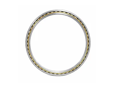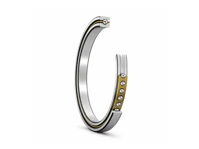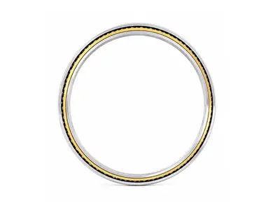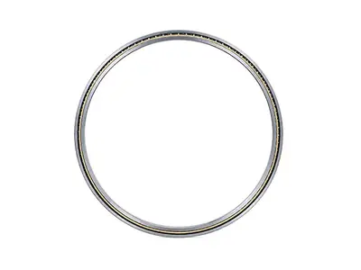
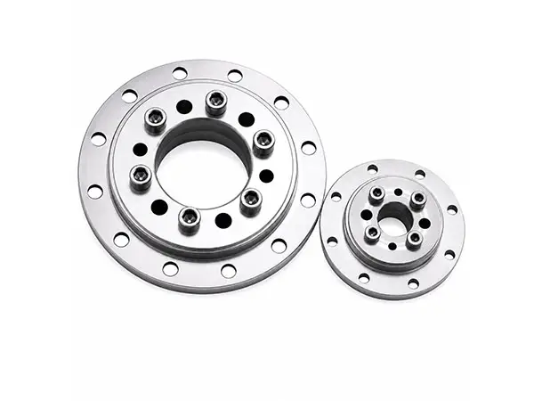
Flanged Thin Section Bearings
Positive Housing Location for Compact Precision SystemsBearing Type: Flanged thin-section double-row angular-contact ball bearing
Model Prefix: HWFAD-prefix models
Flange Design: Integral flange on the outer ring
Load Direction: Combined radial and axial loads
Diameter Ranges: d: 203.2–278 mm; D: 223–303 mm; Df: 237–320 mm
Height & Flange: Overall height H: 12.7–15.875 mm; flange thickness t: 5 mm.
Technical Specifications
| Specification | Details |
|---|---|
| Bearing Type | Flanged thin-section double-row angular-contact ball bearing |
| Model Prefix | HWFAD-prefix models |
| Flange Design | Integral flange on the outer ring |
| Load Direction | Combined radial and axial loads |
| Diameter Ranges | d: 203.2–278 mm; D: 223–303 mm; Df: 237–320 mm |
| Height & Flange | Overall height H: 12.7–15.875 mm; flange thickness t: 5 mm |
| Materials | Stainless-steel rings and balls; polyimide cage |
| Precision | P4 |
| Radial Clearance | 0.011–0.023 mm, model-specific |
| Operating Temperature | -50°C to +100°C for listed models |
| Product Form | Open precision design |
Flanged Thin Section Bearings Overview
Flanged thin section bearings combine a compact bearing cross-section with an integral flange on the outer ring. The flange provides a positive axial locating surface in the housing, simplifies surrounding retention features and helps prevent bearing movement under shock or vibration.
The listed HWFAD models use a precision double-row angular-contact arrangement. Two rows share radial and axial loading, increase system rigidity and support moment loads while retaining the low mass, low rotational torque and high rotational accuracy associated with thin-section bearings.
Flange Function and Thermal Location
Where housing material expands more than the bearing outer ring, elevated temperature may reduce housing-fit tightness. The flange maintains a defined shoulder location and supports reliable axial retention; final fits and shoulder geometry must be selected for the actual temperature, load and housing material.
- Integral flange reduces separate retaining parts
- Positive axial location under vibration and shock
- Compact cross-section saves radial space and mass
- Double-row contact improves rigidity and moment capacity
Mounting and Fit Considerations
Thin rings are sensitive to shaft and housing roundness. Excessive form error can distort the raceways, increase noise and reduce running accuracy. Control bore roundness, shoulder perpendicularity and concentricity, and support the flange evenly around its locating face.
- Avoid excessive interference that consumes internal clearance
- Confirm fit, clearance, preload and lubricant for the duty
- Use the approved drawing for flange shoulder dimensions
Design Summary
| Design Element | Listed Configuration | Customer Benefit |
|---|---|---|
| Outer-ring flange | Integral outer-ring flange | Positive axial location |
| Internal design | Double-row angular contact | Combined-load and moment rigidity |
| Precision | P4 | Accurate and repeatable rotation |
| Materials | Stainless steel + polyimide | Corrosion resistance and low mass |
Materials, Lubrication and Protection
The listed precision models use stainless-steel rings and balls with a polyimide cage and are supplied in an open configuration. Lubrication can be selected for speed, temperature, cleanliness and service-life requirements. Metal shields, contact seals or low-friction non-contact seals may be engineered for selected variants where contamination control is required.
Cage form, lubricant, sealing and material selection should be confirmed together because each choice affects torque, speed capability, temperature range and corrosion resistance.
Typical Applications
- Robot joints and compact rotary axes
- Precision turntables and indexing systems
- Semiconductor and inspection equipment
- Optical, radar and antenna positioning
- Medical imaging and treatment systems
- Aerospace gimbals and compact actuators
Available Models & Specifications
Click on any part number to view detailed CAD drawings and download PDF specifications.