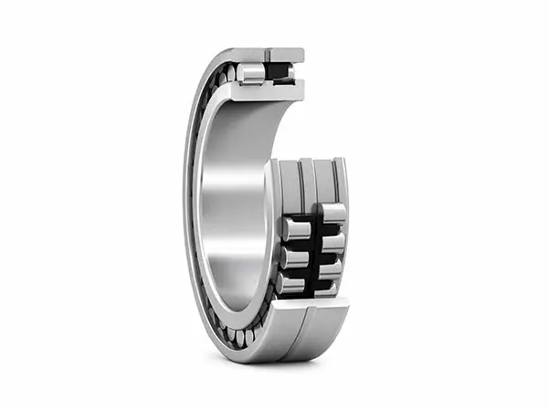
Super-Precision Cylindrical Roller Bearings
CHG super-precision cylindrical roller bearings combine high radial load capacity, high radial stiffness, accurate running and axial displacement capability. They are designed primarily for machine-tool spindles and other precision rotating systems where rigidity, speed and thermal stability must be balanced.
Key Parameters
| Product family | Super-precision cylindrical roller bearings |
|---|---|
| Reference series | N 10 single-row; NN 30 and NNU 49 double-row |
| Load direction | Primarily radial load; axial displacement within the bearing |
| Bore options | Cylindrical or tapered bore according to series; tapered bore commonly 1:12 |
| Typical applications | Machine-tool spindles, machining centers, grinding, milling, turning and precision printing equipment |
Super-precision Cylindrical Roller Bearings Overview
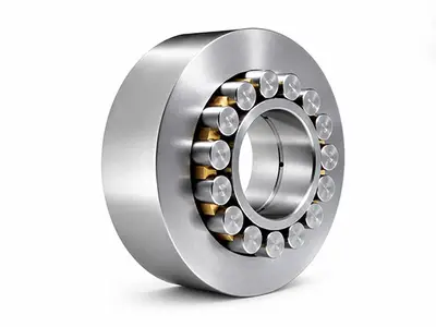
Super-precision cylindrical roller bearings use line contact between rollers and raceways to provide substantially higher radial stiffness than ball bearings of a comparable envelope. Their separable construction supports accurate mounting, while N, NN and NNU internal designs allow axial displacement between shaft and housing without using a loose ring fit.
Key Features and Customer Benefits
High radial stiffness helps stabilize spindle center position under cutting and process loads.
High radial load capacity supports compact, high-performance spindle designs.
Precision raceways and controlled roller geometry support low runout and consistent rotation.
Axial displacement capability allows the bearing to serve as a non-locating support and accommodate thermal shaft growth.
Tapered-bore designs permit radial clearance or preload to be adjusted by controlled axial drive-up.
Separable rings simplify mounting, inspection and dismounting of precision spindle assemblies.
Product Series Selection
Select the dimensional series according to speed, radial stiffness, load, available radial space and shaft diameter. The table is a series-level guide; exact dimensions, load ratings, speed limits, bore and cage must be confirmed for the selected size.
Product Series Selection
| Series | Rows & design | Speed potential | Stiffness & capacity | Typical selection |
|---|---|---|---|---|
| N 10 | Single row, N design | Very high | High stiffness with low section | High-speed non-locating spindle position |
| NN 30 | Double row, NN design | High | Very high radial stiffness and capacity | Machine-tool spindles requiring rigidity |
| NNU 49 | Double row, NNU design / 双列NNU型 | Moderate to high | High capacity with low section | Precision cylinders, printing and large spindle supports |
Internal Design and Axial Displacement
These bearings are intended primarily for radial loads. The flange arrangement guides the rollers and determines which ring can be separated. Because one ring has no integral flanges, the shaft can move axially relative to the housing within the bearing, making the design suitable for non-locating positions.
Technical Specifications
| Design | Roller guidance | Separable component | Application effect |
|---|---|---|---|
| N / N | Inner-ring flanges | Outer ring | Single-row, compact radial support |
| NN / NN | Inner-ring flanges | Outer ring | Double-row high radial stiffness |
| NNU / NNU | Outer-ring flanges | Inner ring | Double-row design for selected mounting layouts |
Axial Locating Note
N, NN and NNU cylindrical roller bearings do not normally locate the shaft axially. Use an angular contact ball bearing set, thrust bearing or another suitable locating arrangement to carry axial load and define axial position.
Bore Type and Clearance or Preload Adjustment
Cylindrical-bore bearings rely on manufacturing tolerances, fits and selected clearance. Tapered-bore bearings allow the effective raceway diameter to be increased by driving the inner ring onto a tapered shaft seat or sleeve. This reduces radial internal clearance and can establish a defined operating clearance or radial preload.
Cylindrical bore: Fit and supplied clearance determine the mounted condition
Tapered bore: Controlled axial drive-up enables fine clearance or preload adjustment
Drive-up verification: Measure clearance reduction, axial position or a validated dimensional indicator
Operating condition: Include fit expansion, speed, centrifugal effects and temperature gradient
Avoid uncontrolled negative clearance
Excessive drive-up or preload can increase friction, heat and roller edge stress, and may cause seizure. The target mounted clearance or preload must be calculated and verified for the complete spindle.
Precision, Radial Stiffness and Runout
The performance of a precision spindle depends on bearing raceway accuracy, roller geometry, ring runout, shaft and housing accuracy, fits and mounting procedure. CHG can review SP-, UP- or application-defined precision requirements according to size and inspection agreement. Final tolerances must be stated on the approved drawing or technical specification.
Running accuracy
Radial and axial runout control supports stable spindle rotation
Radial stiffness
Line contact and multiple rollers limit elastic displacement
Ring marking
High point, orientation or matching marks can be supplied when agreed
Inspection
Dimensional, runout, clearance and material reports available by specification
Materials, Cages and Hybrid Designs
Bearing rings and steel rollers: High-quality bearing steel with controlled heat treatment and precision finishing
Hybrid rollers: Silicon-nitride ceramic rollers may be evaluated for selected high-speed designs
N 10 high-speed cage: Outer-ring-centred window-type engineered polymer/PEEK design according to size
Double-row cages: Machined brass or engineered polymer according to series, speed and temperature
Lubrication, Cooling and Minimum Load
Grease lubrication: Simple and clean; quantity, distribution and run-in must be controlled for high speed.
Oil-air lubrication: Supports high speed and directed lubricant delivery with limited churning.
Cooling: Housing and spindle cooling should control ring temperature differences and preload change.
Minimum load: Adequate radial load is required to reduce roller slip, smearing and cage instability.
Speed is a system limit
Permissible spindle speed depends on bearing size, clearance or preload, cage, lubrication, cooling, load, fits, balance and required life. Catalogue reference speed is not automatically the final spindle speed limit.
Application Areas
High-speed machining centers and motorized spindles
Grinding, milling, turning and boring spindles
Non-tool-end spindle supports requiring thermal displacement
Precision printing, coating and cylinder equipment
High-speed test rigs, dynamometers and precision rotating machinery
Large-shaft precision equipment requiring high radial stiffness
Selection Workflow
Define shaft diameter, available envelope and required dimensional series.
Provide radial load, load spectrum, speed, acceleration and duty cycle.
Select single-row or double-row design according to speed, capacity and stiffness.
Confirm the non-locating function, required axial displacement and separate locating bearing.
Choose cylindrical or tapered bore and establish the target mounted clearance or preload.
Select precision, cage, steel/hybrid rollers, lubrication and cooling.
Verify fits, shoulders, clamping, assembly measurement and run-in procedure.
Installation and Operating Guidelines
Keep bearings, tools and assembly areas extremely clean.
Measure shaft and housing roundness, cylindricity, coaxiality and shoulder squareness.
Support and align separable rings carefully; do not damage rollers or raceway edges.
For tapered bores, control drive-up using the approved clearance-reduction or dimensional method.
Apply mounting force only to the fitted ring and use approved heating or hydraulic tools.
Run in under controlled speed steps while monitoring temperature, vibration, noise and drive power.
Customization and Engineering Support
Non-standard dimensions, ring geometry and lubrication features
Precision, radial clearance or preload and high-point marking
Steel or hybrid ceramic roller designs
Special cages, coatings, materials and operating-temperature solutions
Application calculation, drawing review, inspection and traceability documents
CHG Bearing provides application engineering and customized super-precision bearing development from Luoyang. We can review the complete spindle arrangement before quotation and support prototype validation through batch production.
Information Required for Quotation
Bearing designation or d × D × B dimensions and series
Spindle drawing, locating/non-locating positions and axial displacement
Maximum and continuous speed, acceleration and duty cycle
Radial load, load spectrum, shock and target life
Required precision, runout, stiffness and mounted clearance/preload
Lubrication, cooling, temperature and contamination conditions
Quantity, destination country, certificates and delivery date
Available Models & Specifications
Click on any part number to view detailed CAD drawings and download PDF specifications.