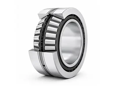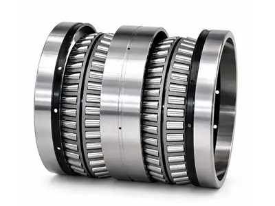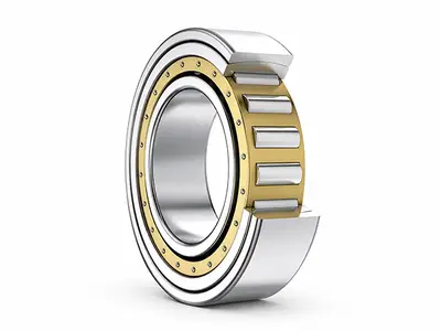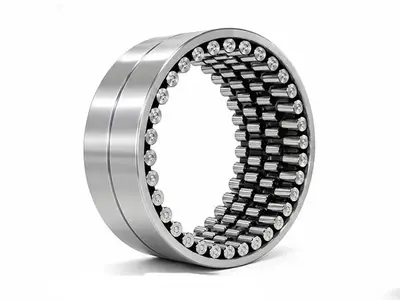
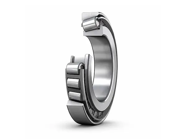
Single Row Tapered Roller Bearings
Separable Bearings for Combined Radial and Axial LoadsBearing Type: Single Row Tapered Roller Bearing
Series: 30000 Type (7000 Series)
Bore Diameter: 100–950 mm; customizable within scope
Width: Customizable
Load Capacity: High combined-load capacity
Primary Load: Radial-dominant combined radial and axial load.
Technical Specifications
| Specification | Details |
|---|---|
| Bearing Type | Single Row Tapered Roller Bearing |
| Series | 30000 Type (7000 Series) |
| Bore Diameter | 100–950 mm; customizable within scope |
| Outer Diameter | 270–1250 mm |
| Width | Customizable |
| Load Capacity | High combined-load capacity |
| Primary Load | Radial-dominant combined radial and axial load |
| Large Contact Angle | 27°–30°; axial-dominant combined load |
| Material | GCr15 / GCr15SiMn / G20Cr2Ni4A |
| Design | Separable inner and outer rings |
| Axial Location | One direction |
| Sealing | Optional seals available |
Single Row Tapered Roller Bearings Overview
Single row tapered roller bearings are designed primarily for combined radial and axial loads in which the radial component is dominant. Large-contact-angle designs of 27° to 30° can carry combined loads with a larger axial component, but are generally not intended for pure axial loading.
The bearing can limit axial displacement of the shaft or housing in one direction and therefore acts as a unidirectional locating bearing. Because the cone assembly and cup are separable, they can be installed independently, and cups of the same specification can be interchanged for convenient mounting and removal.
Combined Load Capacity
The tapered raceways and rollers generate a load-carrying geometry that supports radial and axial forces simultaneously. The contact angle determines the axial capacity: a larger angle increases the axial load component that the bearing can accommodate.
- Radial-dominant combined loading
- Large-angle designs for higher axial components
- One-direction axial location
- High stiffness under preload
Separable Design and Adjustable Clearance
Radial and axial clearance can be adjusted during mounting and operation, and preload may be applied to increase stiffness. Correct adjustment is essential: insufficient clearance raises temperature, while excessive clearance increases vibration and reduces rotational accuracy.
- Independent installation of cone and cup
- Interchangeable cups of the same specification
- Adjustable clearance and preload
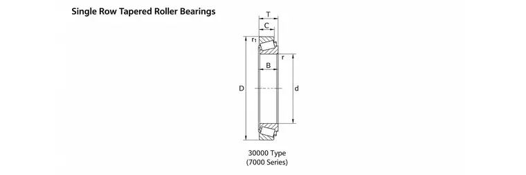
Single row tapered roller bearing — 30000 Type (7000 Series)
Bearing Design and Arrangement
| Design | Configuration | Load and Function |
|---|---|---|
| Standard single row | Separable cone assembly and cup | Radial-dominant combined load; one-direction axial location |
| Large contact angle | Contact angle 27°–30° | Combined load with a larger axial component |
| Matched pair | Two single-row bearings arranged in opposing directions | Balances induced axial forces and locates in both directions |
Mounting and Operating Guidance
Shaft inclination relative to the housing bore should be avoided because edge stress between rollers and raceways can cause premature damage. Only a very small inclination of up to 2 arcminutes is permissible when corrected line contact is provided. Under radial load, induced axial force normally requires two single-row bearings to be mounted in opposing directions.
Permissible inclination: ≤ 2 arcmin (with corrected line contact)
Typical Applications
- Automotive rear axle hubs
- Large machine-tool spindles
- High-power gear reducers
- Conveyor and feedway rollers
- Heavy industrial transmissions
- Paired locating arrangements
Available Models & Specifications
Click on any part number to view detailed CAD drawings and download PDF specifications.