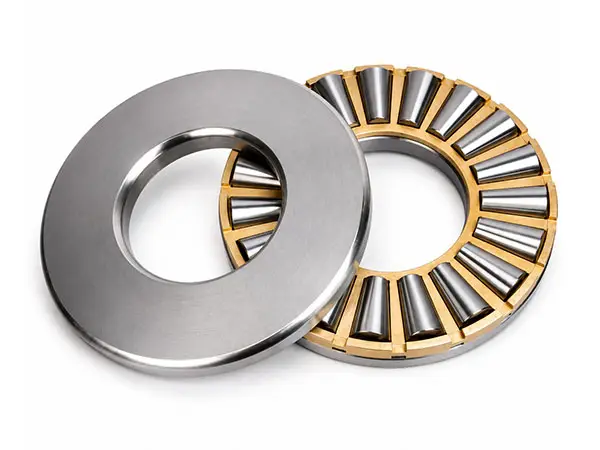
Tapered Roller Thrust Bearings
High-Capacity Bearings for Single- and Double-Direction Axial LoadsBearing Type: Tapered Roller Thrust Bearing
Size Range: d 200-380 mm; D 400-670 mm; 75-274 kg
Design Types: Single-direction 90000 Type (19000 Series); double-direction arrangement
Primary Load: High axial load
Locating Function: Single-direction axial location for standard design.
Technical Specifications
| Specification | Details |
|---|---|
| Bearing Type | Tapered Roller Thrust Bearing |
| Size Range | d 200-380 mm; D 400-670 mm; 75-274 kg |
| Design Types | Single-direction 90000 Type (19000 Series); double-direction arrangement |
| Primary Load | High axial load |
| Locating Function | Single-direction axial location for standard design |
| Load Comparison | Higher capacity than cylindrical roller thrust bearings |
| Sliding & Speed | Lower relative sliding; lower limiting speed |
| Material | GCr15 or G20Cr2Ni4A |
| Cage | Solid steel or brass cage |
| Temperature & Precision | Up to 150°C (302°F); P0/P6/P5/P4 customizable |
| Lubrication | Grease or oil |
Tapered Roller Thrust Bearings Overview
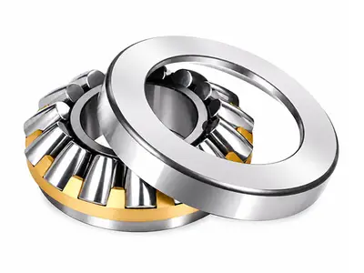
Standard single-direction tapered roller thrust bearings carry axial load in one direction only and limit axial displacement of the shaft in the same direction, making them suitable as single-direction axial locating bearings.
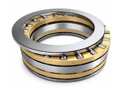
Compared with cylindrical roller thrust bearings, their tapered contact geometry provides higher load capacity and less relative sliding, but the limiting speed is lower. Double-direction arrangements shown in the structure figure use opposed rows to support thrust in both directions.
High Axial Capacity and Locating Function
The tapered rollers and raceways form a rigid load path for demanding thrust positions. The standard single-direction design supports heavy axial load and accurately controls axial movement in one direction, while the double-direction arrangement extends axial support to both directions.
High axial load capacity
- Single-direction axial location
- Higher capacity than cylindrical thrust bearings
- Rigid tapered roller contact
Sliding, Speed and Cage Characteristics
Tapered contact reduces relative sliding compared with cylindrical roller thrust designs, but these bearings remain intended for moderate- or low-speed thrust service. Solid steel or brass cages are normally selected according to bearing size, load, temperature and lubrication conditions.
- Lower relative sliding
- Lower limiting speed
- Solid steel or brass cage

Single- and double-direction tapered roller thrust bearing structures
Single- and Double-Direction Structures
| Option | Configuration | Selection Guidance |
|---|---|---|
| Single-Direction | 90000 Type (19000 Series) | One-direction thrust and axial location |
| Double-Direction | Opposed double-row thrust structure | Supports thrust in both directions |
| Cage Options | Solid steel or brass | Select by load, temperature and lubrication |
Mounting and Operating Considerations
Confirm the required thrust direction before mounting and keep bearing washers correctly aligned. Use the specified grease or oil supply and control operating temperature. Because limiting speed is relatively low, verify speed, lubrication and heat dissipation for continuous service.
Bore diameter range: 200-380 mm
Typical Applications
- Construction machinery
- Automotive systems
- Power-generation equipment
- Single-direction axial locating positions
- High axial-load machinery
- Low-speed thrust-bearing positions