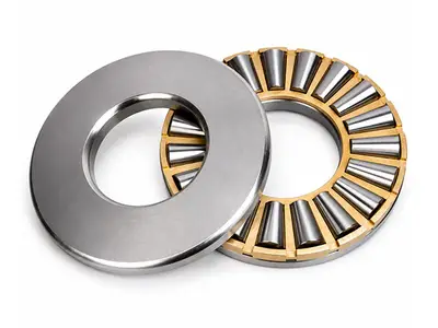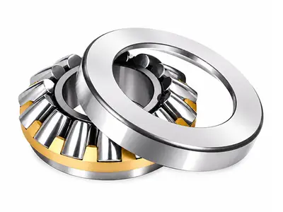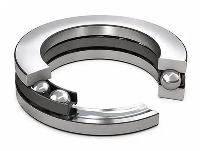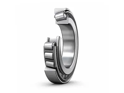
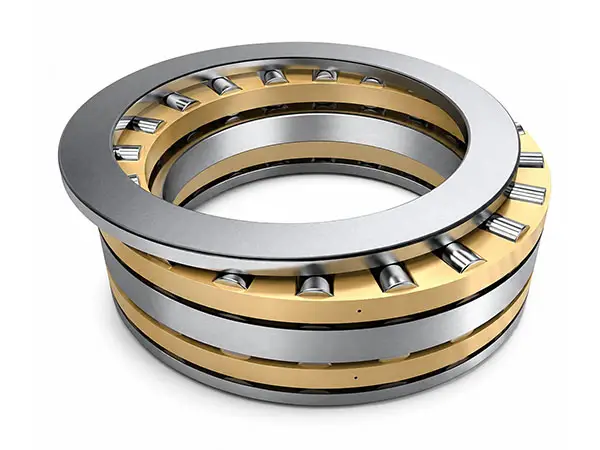
Cylindrical Roller Thrust Bearings
Separable High-Capacity Bearings for Single-Direction Axial LoadsBearing Type: Cylindrical Roller Thrust Bearing
Size Range: d 200-380 mm; D 400-670 mm; 75-274 kg
Series: 80000 Type (9000 Series)
Primary Load: High single-direction axial load
Shock Load: Limited shock load
Locating Function: Single-direction axial location.
Technical Specifications
| Specification | Details |
|---|---|
| Bearing Type | Cylindrical Roller Thrust Bearing |
| Size Range | d 200-380 mm; D 400-670 mm; 75-274 kg |
| Series | 80000 Type (9000 Series) |
| Primary Load | High single-direction axial load |
| Shock Load | Limited shock load |
| Locating Function | Single-direction axial location |
| Speed Capability | Lower limiting speed; suited to low-speed duty |
| Separability | Separable bearing |
| Material | GCr15, GCr15SiMn or G20Cr2Ni4A |
| Cage | Machined metal solid cage; alternatives on request |
| Precision, Temperature & Certification | High precision; up to 200°C by configuration; ISO 9001, ISO 14001 |
Cylindrical Roller Thrust Bearings Overview
Cylindrical roller thrust bearings are separable bearings designed primarily for axial loads in one direction. They can also accommodate limited shock loading and can restrict axial displacement of a shaft or housing in one direction, serving as single-direction axial locating bearings.
For the same envelope size, their axial load capacity is considerably higher than that of thrust ball bearings. During rolling, the different linear velocities at the two ends of each roller cause unavoidable sliding on the raceways, so the limiting speed is lower and the bearing is normally selected for low-speed operation.
High Axial Load Capacity and Location
The line-contact geometry between cylindrical rollers and raceways provides high load-carrying capacity and rigidity in the axial direction. The bearing supports axial force in one direction and locates the shaft or housing on the same side while its separable components simplify installation and inspection.
- High single-direction axial load capacity
- Higher capacity than same-size thrust ball bearings
- Single-direction axial locating function
- Separable construction
Sliding Characteristics and Speed Limit
Because the roller ends travel at different linear velocities, some sliding occurs between the rollers and raceways even during normal operation. Correct lubrication and accurate alignment are essential for controlling heat and wear. These bearings therefore have lower limiting speeds and are intended mainly for low-speed, heavy-duty applications.
- Unavoidable raceway sliding
- Lower limiting speed
- Best suited to low-speed heavy-duty operation
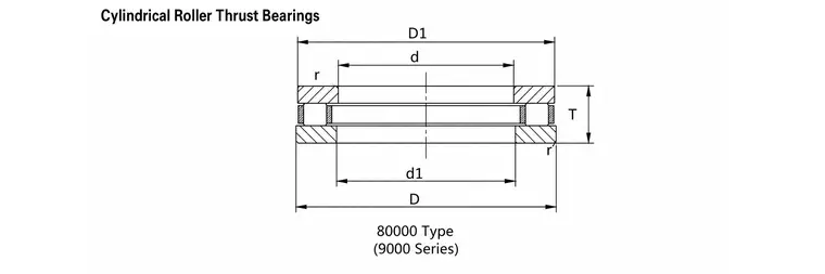
Cylindrical roller thrust bearing principal dimensions
80000 Type Structure and Cage Options
| Option | Configuration | Selection Guidance |
|---|---|---|
| 80000 Type | 9000 Series separable thrust arrangement | For single-direction axial load and location |
| Standard Cage | Machined metal solid cage | Standard production configuration |
| Custom Cage | Alternative cage types or materials | Available according to operating requirements |
Mounting and Operating Considerations
Keep the shaft and housing washers accurately aligned and provide lubrication suitable for the expected sliding, load and temperature. Confirm that the bearing is loaded only in its intended axial direction. Cage material and high-temperature capability should be selected together with lubricant and operating speed.
Bore diameter range: 200-380 mm
Typical Applications
- Heavy-duty machine tools
- Large marine gearboxes
- Oil-drilling rigs
- Vertical electric motors
- Low-speed axial locating positions
- Machinery with limited shock loading