Dreireihige Zylinderrollen-Drehlager
Drei unabhängige Rollenreihen tragen axiale Lasten, radiale Lasten und Kippmomente über spezielle Laufbahnen – und sorgen so für außergewöhnliche Tragfähigkeit und strukturelle Steifigkeit bei Maschinen mit großem Durchmesser.
Struktur und Funktionsprinzip
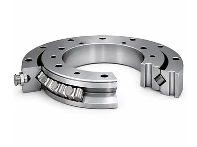
Das dreireihige Zylinderrollen-Drehlager besteht aus drei Lagerringen mit voneinander getrennter oberer axialer Laufbahn, unterer axialer Laufbahn und radialer Laufbahn. Zwei horizontale Rollenreihen übertragen primär axiale Lasten und Kippmomente, während die vertikale Rollenreihe hauptsächlich radiale Lasten aufnimmt und die Rotation führt.
Da jede Lastkomponente von einer separaten Rollenreihe getragen wird, lässt sich der Lastpfad präzise definieren und das Lager erreicht eine sehr hohe Tragfähigkeit, Steifigkeit und Betriebsstabilität. Die Konstruktion eignet sich besonders dort, wo ausreichend Bauraum für einen großen, starren Lagerquerschnitt vorhanden ist.
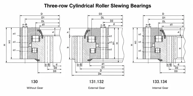
Verfügbare Strukturversionen
| Series | Gear version | Customer-facing selection point |
|---|---|---|
| 130 | Gearless | For systems driven by a separate mechanism or without an integral ring gear |
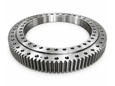
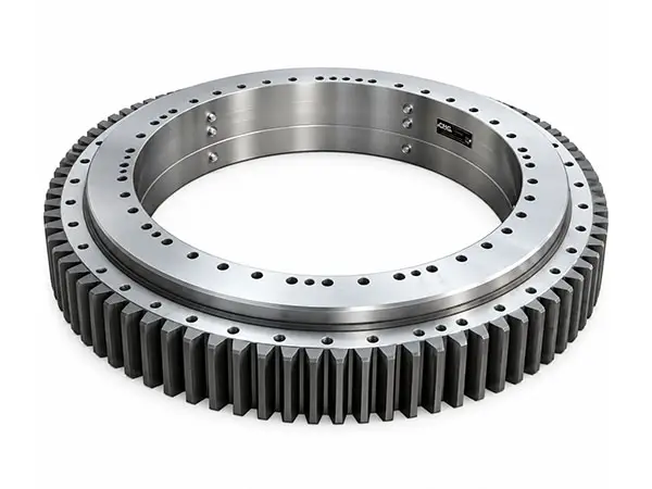
| 131 / 132 | External gear | Easy access for pinion drive and inspection |
| 133 / 134 | Internal gear | Compact protected gearing with the pinion inside the bearing envelope |
Katalogsortiment
| Parameter | Catalog range | Notes |
|---|---|---|
| Bearing type | Three-row cylindrical roller slewing bearing | Metric, application-engineered |
| Bore diameter d | 576–5230 mm | Across current CHG product table |
| Outside diameter D | 844–5940 mm | Gear tip diameter may differ |
| Overall height H | 125–430 mm | Dependent on ring and raceway design |
| Reference mass | 290–16,722 kg | Varies with size and gear arrangement |
| Gear module m | External: 6–28; Internal: 14–25.4 | Gearless versions omit m |
| Number of teeth z | External: 108–270; Internal: 89–219 | Final drawing governs |
| Gear width b | External: 80–270 mm; Internal: 107–266.7 mm | Can be project-specific |
| Lubrication & sealing | Distributed grease ports; integral seals | Port thread and seal material by design |
Leitfaden zur Designauswahl
- Lastfall – Definition der maximalen Axiallast, Radiallast und des Kippmoments unter Berücksichtigung von Betriebs-, Park-, Notfall- und Transportbedingungen.
- Getriebeanordnung – je nach Antriebslayout, Schutz, Inspektionszugänglichkeit und verfügbarem Bauraum wählen Sie getriebelos, mit Außenverzahnung oder mit Innenverzahnung.
- Zahnradkonstruktion – Modul, Zähnezahl, Eingriffswinkel, Zahnradqualität, Zahnflankenspiel, Ritzeldaten und Belastungsspektrum festlegen; Zahnfuß- und Zahnflankenfestigkeit überprüfen.
- Montageschnittstelle – Stützsteifigkeit, Ebenheit, Schraubenfestigkeitsklasse, Anzugsmethode und Lochanordnung prüfen. Durchgangsbohrungen oder Gewindebohrungen können realisiert werden.
- Schmierung und Abdichtung – Sorgen Sie für gut zugängliche, gleichmäßig verteilte Schmierstellen und wählen Sie Fette und Dichtungsmaterialien passend zur Umgebung und Temperatur.
Katalog-Engineering-Hinweise
| Item | Guidance |
|---|---|
| Lubrication holes n1 | Lubrication holes n1 are evenly distributed; the corrected catalog lists the applicable quantity for each model. Lubrication-port thread and interface are model-specific and shall follow the current parameter table and approved drawing |
| Mounting holes | The corrected catalog identifies the outer- and inner-ring mounting-hole pitch-circle diameters as D1 and D2. Hole quantities and through-hole/threaded specifications are model-specific; project drawings govern. |
| Gear force | Where a table lists maximum pitch-circle tangential force, the catalog rated tangential force is typically taken as one half; confirm against the selected model calculation. |
| Internal-gear correction | Some standard Series 13 internal-gear designs use an addendum modification coefficient of 0.2; the workbook and approved drawing define the actual value. |
Typische Anwendungen
Schaufelradbagger
Raupen- und Mobilkrane
Schiffs- und Hafenkräne
Gießpfannentürme und Stahlherstellungsanlagen
Tunnelbohrmaschinen
Direkt angetriebene Hauptwellen von Windkraftanlagen
Für ein Angebot benötigte Informationen
| Category | Please provide |
|---|---|
| Loads | Axial, radial and overturning moment loads; load spectrum and safety factors |
| Dimensions | Required d, D and H; available installation envelope and support-ring dimensions |
| Drive | Gearless/external/internal gear; module, teeth, pinion, ratio, backlash and torque |
| Operation | Speed, duty cycle, acceleration, shock, temperature, contamination and corrosion |
| Interfaces | Bolt-hole pattern, bolt grade, lubrication ports, seals and special coatings |
| Life & standards | Required service life, inspection criteria, certification and traceability requirements |
Verfügbare Modelle und Spezifikationen
Klicken Sie auf eine beliebige Teilenummer, um detaillierte CAD-Zeichnungen anzuzeigen und PDF-Spezifikationen herunterzuladen.